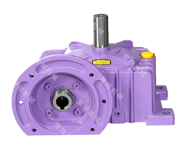
WP
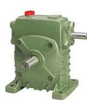
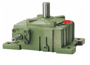
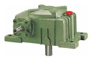
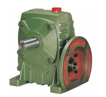
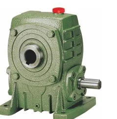
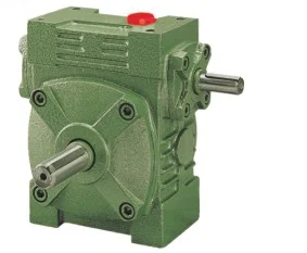
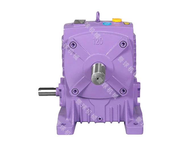
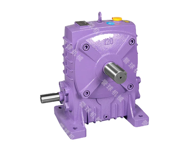
WP series worm gear reducers (single stage)
Classic single-stage worm gear reducers in a cast-iron housing: 13 sizes with centre distances from 40 to 250 mm and ratios from 5 to 100. Versions differ in the arrangement of input and output shafts, an optional motor flange and an optional hollow output shaft.
- Sizes (centre distance)
- 40–250 mm (13 sizes)
- Ratio
- 5, 10, 15, 20, 25, 30, 40, 50, 60, 70, 80, 100 (K versions: 5–60)
- Input power (i = 10–60, 1500 r/min)
- 0.12–33.2 kW
- Output torque
- 19–2745 N·m
- Motor power (D versions)
- 0.12–15 kW
- Input shaft diameter
- 12–60 mm
- Output shaft diameter (WPA)
- 14–90 mm
- Efficiency
- 77–90 % at i = 10; 60–71 % at i = 60
- Input shaft speed
- typically 600–1800 r/min, max. 2000 r/min
- Weight (WPA)
- 4–360 kg
- Lubrication
- N220–N320 oil (−30 to 40 °C) or N320–N460 (40–65 °C); first change after 100 h, then every 2500 h
- Max. oil temperature
- 95 °C
Features
- 13 sizes: centre distance 40, 50, 60, 70, 80, 100, 120, 135, 147, 155, 175, 200, 250 mm
- Input shaft below (A) or above (S), output shaft upward (O) or downward (X); the universal W housing also allows T and V
- D version with motor flange (gearmotor), motor power from 0.12 to 15 kW
- K version with hollow output shaft for direct mounting on the driven shaft
- Worms are right-hand as standard; left-hand thread available on special request
- Ratings are given for 1500 r/min input speed and 8 h/day operation under steady load
- AS, TV and OX base plates available as accessories
Designation
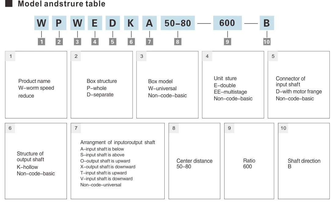
WPWEDKA50-80—600—B
| W | Product name: worm speed reducer |
|---|---|
| P / D | Housing structure: P — one-piece, D — split |
| W / — | Housing model: W — universal, no code — basic |
| E / EE / — | Stages: E — double, EE — multi-stage, no code — single (basic) |
| D / — | Input connection: D — motor flange, no code — basic input shaft |
| K / — | Output shaft: K — hollow, no code — basic (solid) |
| A / S / O / X / T / V | Shaft arrangement: A — input shaft below, S — input shaft above, O — output shaft upward, X — output shaft downward, T — input shaft upward, V — input shaft downward; no code — universal |
| 50-80 | Centre distance (for double-stage units, the pair of stages) |
| 600 | Ratio |
| B | Shaft direction (diagram A–F for each type) |
Versions
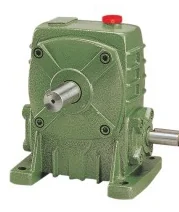
| WPA | Input shaft below, solid output shaft |
|---|---|
| WPS | Input shaft above |
| WPO | Output shaft pointing upward (vertical) |
| WPX | Output shaft pointing downward (vertical) |
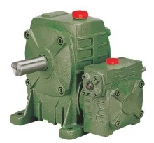
| WPDA / WPDS / WPDO / WPDX | The same arrangements with a motor flange |
| WPKA / WPKS / WPDKA / WPDKS | Hollow output shaft, with input shaft or motor flange |
| WPZ / WPDZ / WPKZ / WPDKZ | Z versions (vertical input shaft; WPDZ/WPDKZ with motor flange on top) |
| WPW… (WPWA, WPWS, WPWO, WPWX, WPWT, WPWV, WPWD…, WPWK…, WPWDK…) | Universal W housing with A, S, O, X, T, V shaft arrangements, with motor flange and/or hollow shaft |
| WD | Separate WD type (specified by gear module, i = 10–60) — see uncertain |
Technical data
WP, WPK, WPW, WPWK (A, S, X, O, T, V): input shaft power, kW (input 1500 r/min)
| Size | i = 10 | i = 15 | i = 20 | i = 25 | i = 30 | i = 40 | i = 50 | i = 60 |
|---|---|---|---|---|---|---|---|---|
| 40 | 0.40 | 0.33 | 0.26 | 0.24 | 0.22 | 0.16 | 0.14 | 0.12 |
| 50 | 0.65 | 0.52 | 0.40 | 0.37 | 0.34 | 0.27 | 0.24 | 0.20 |
| 60 | 1.00 | 0.82 | 0.65 | 0.59 | 0.54 | 0.45 | 0.40 | 0.32 |
| 70 | 1.60 | 1.35 | 1.10 | 0.96 | 0.82 | 0.67 | 0.61 | 0.52 |
| 80 | 2.20 | 1.78 | 1.36 | 1.28 | 1.20 | 0.90 | 0.80 | 0.75 |
| 100 | 3.60 | 3.10 | 2.60 | 2.35 | 2.10 | 1.68 | 1.30 | 1.00 |
| 120 | 5.20 | 4.35 | 3.50 | 3.25 | 3.00 | 2.20 | 1.90 | 1.50 |
| 135 | 9.75 | 7.85 | 6.00 | 5.50 | 5.00 | 3.69 | 2.89 | 2.30 |
| 147 | 10.71 | 8.43 | 6.18 | 5.71 | 5.23 | 3.84 | 3.09 | 2.52 |
| 155 | 12.80 | 9.90 | 7.00 | 6.53 | 6.00 | 4.40 | 3.61 | 3.00 |
| 175 | 17.30 | 13.60 | 10.00 | 9.13 | 8.30 | 6.18 | 4.85 | 4.07 |
| 200 | 22.60 | 18.20 | 13.86 | 12.75 | 11.67 | 8.78 | 6.71 | 5.58 |
| 250 | 33.20 | 27.40 | 21.60 | 20.00 | 18.43 | 14.00 | 10.43 | 8.62 |
WP, WPK, WPW, WPWK (A, S, X, O, T, V): output shaft torque, N·m (input 1500 r/min)
| Size | i = 10 | i = 15 | i = 20 | i = 25 | i = 30 | i = 40 | i = 50 | i = 60 |
|---|---|---|---|---|---|---|---|---|
| 40 | 19 | 23 | 20 | 25 | 25 | 20 | 22 | 20 |
| 50 | 31 | 36 | 32 | 38 | 39 | 36 | 37 | 35 |
| 60 | 50 | 58 | 56 | 68 | 62 | 71 | 75 | 59 |
| 70 | 83 | 98 | 101 | 112 | 99 | 104 | 113 | 97 |
| 80 | 113 | 133 | 120 | 149 | 151 | 140 | 145 | 146 |
| 100 | 193 | 237 | 258 | 284 | 277 | 291 | 257 | 229 |
| 120 | 262 | 336 | 361 | 404 | 413 | 392 | 399 | 355 |
| 135 | 540 | 622 | 619 | 696 | 707 | 667 | 626 | 562 |
| 147 | 586 | 676 | 637 | 727 | 739 | 694 | 669 | 616 |
| 155 | 709 | 785 | 722 | 842 | 848 | 784 | 770 | 791 |
| 175 | 958 | 1091 | 1044 | 1221 | 1189 | 1133 | 1127 | 1078 |
| 200 | 1280 | 1477 | 1482 | 1643 | 1782 | 1654 | 1516 | 1449 |
| 250 | 1881 | 2266 | 2310 | 2579 | 2745 | 2674 | 2357 | 2371 |
WPD, WPDK, WPWD, WPWDK (motor flange): motor power and output torque (AO2 or Y series motors, 1500 r/min)
| Size | Motor, kW (i = 10–30) | Motor, kW (i = 40–60) | T2, N·m, i = 10 | i = 15 | i = 20 | i = 25 | i = 30 | i = 40 | i = 50 | i = 60 |
|---|---|---|---|---|---|---|---|---|---|---|
| 40 | 0.12 | 0.12 | 6 | 8 | 9 | 13 | 14 | 15 | 19 | 20 |
| 50 | 9 | 12 | 14 | 19 | 20 | 24 | 28 | 34 | ||
| 60 | 0.37 | 0.37 | 19 | 26 | 34 | 42 | 42 | 58 | 67 | 73 |
| 70 | 0.75 | 0.37 | 39 | 54 | 70 | 87 | 95 | 58 | 68 | 70 |
| 80 | 1.5 | 0.75 | 77 | 112 | 142 | 174 | 189 | 117 | 136 | 146 |
| 100 | 1.5 | 1.5 | 80 | 115 | 149 | 181 | 198 | 260 | 307 | 344 |
| 120 | 3 | 2.2 | 151 | 232 | 310 | 372 | 413 | 392 | 480 | 521 |
| 135 | 4 | 3 | 219 | 321 | 413 | 509 | 565 | 542 | 649 | 690 |
| 147 | 4 | 3 | 219 | 321 | 413 | 509 | 565 | 542 | 649 | 690 |
| 155 | 5.5 | 4 | 305 | 411 | 525 | 709 | 760 | 713 | 853 | 1039 |
| 175 | 7.5 | 5.5 | 415 | 602 | 783 | 1002 | 1074 | 1008 | 1278 | 1450 |
| 200 | 11 | 7.5 | 623 | 892 | 1176 | 1417 | 1680 | 1413 | 1695 | 1948 |
| 250 | 15 | 11 | 850 | 1246 | 1604 | 1933 | 2234 | 2101 | 2486 | 3025 |
Data from the manufacturer’s catalogue. Full selection tables and dimension drawings are in the PDF catalogue.
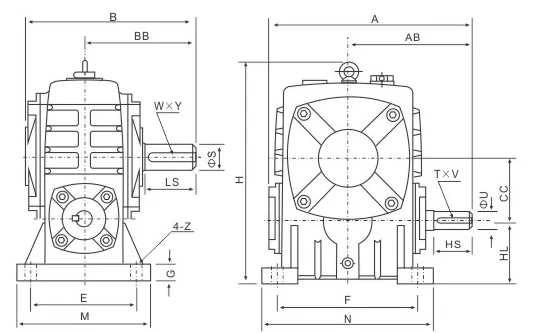
Drawings