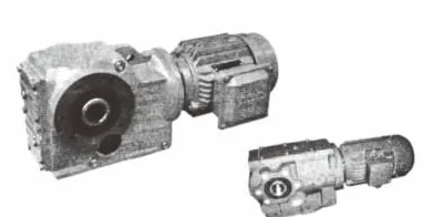
YQK
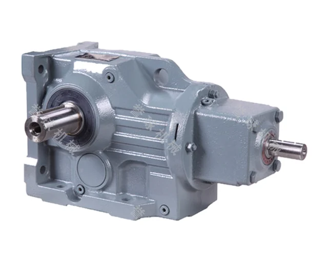
YQK helical-bevel geared motors
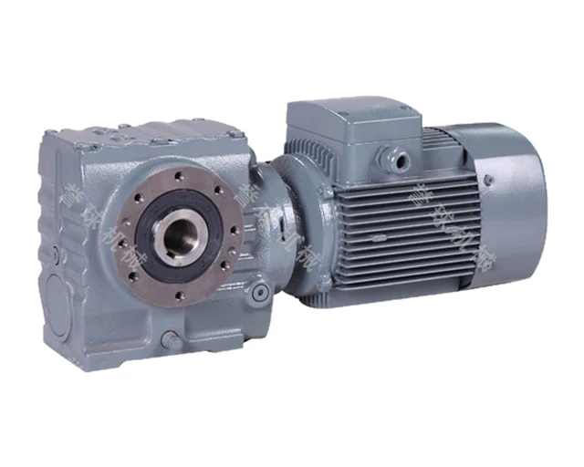
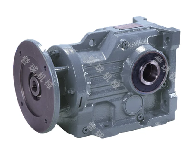
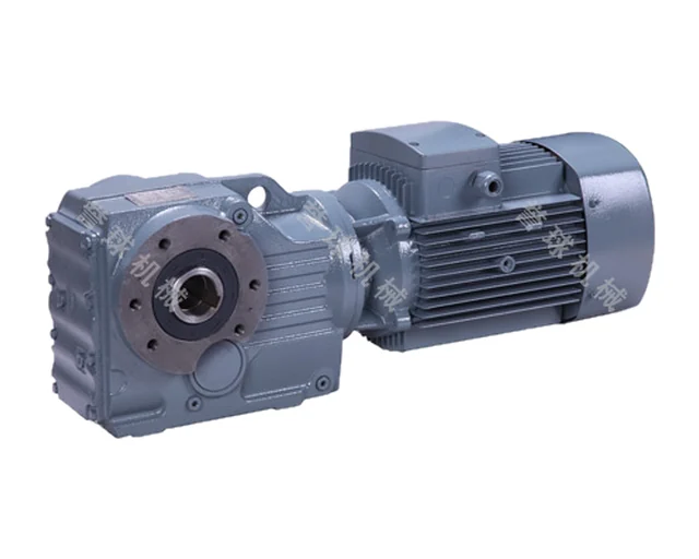
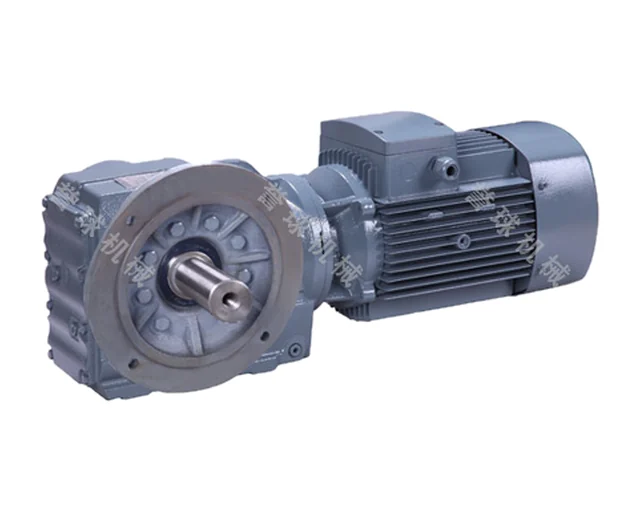
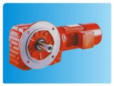
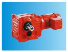
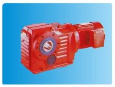
YQK are right-angle geared motors built from helical and bevel stages for high-torque duty. Twelve sizes, 37 to 187, cover 0.18–200 kW input power and permissible torque from 200 to 50000 Nm. Solid or hollow shaft, foot, flange, short-flange and torque-arm versions are offered.
- Sizes
- 37, 47, 57, 67, 77, 87, 97, 107, 127, 157, 167, 187
- Input power
- 0.18–200 kW
- Ratio (single unit)
- 5.36–197.37
- Permissible output torque
- 200–50000 Nm
- Gear unit weight
- 11–1700 kg (mean values)
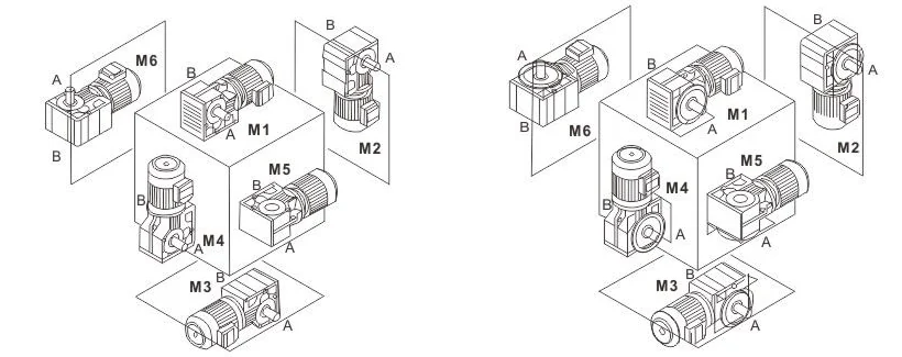
- Mounting positions
- M1–M6
- Terminal box position
- 0°, 90°, 180°, 270°
- Output shaft rotation
- CW / CCW, viewed on the output shaft
- Input speed in combined-unit tables
- 1400 r/min
Features
- Right-angle layout with bevel stage, output at 90° to the motor
- 12 sizes from 37 to 187, permissible torque up to 50000 Nm
- Input power from 0.18 to 200 kW
- Solid or hollow output shaft; hollow shaft also available foot-mounted (KAB)
- Foot, flange, short-flange or torque-arm mounting
- Shaft-input versions and combinations with an R unit (K..R..) for low output speeds
- Six mounting positions M1–M6, terminal box 0°/90°/180°/270°, rotation CW/CCW on order
Designation
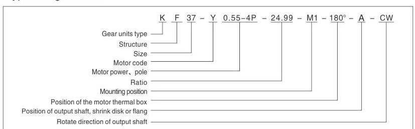
KF37-Y0.55-4P-24.99-M1-180°-A-CW
| K | gear unit type: helical-bevel |
|---|---|
| F | structure (see variants) |
| 37 | size |
| Y | motor code |
| 0.55-4P | motor power (kW) and poles |
| 24.99 | ratio |
| M1 | mounting position |
| 180° | terminal box position |
| A | side of output shaft, shrink disc or flange: A left, B right (viewed from motor end), A+B both |
| CW | output shaft rotation: CW clockwise, CCW counter-clockwise |
Versions
| K | foot-mounted, solid output shaft |
|---|---|
| KA | hollow output shaft |
| KAB | foot-mounted, hollow shaft |
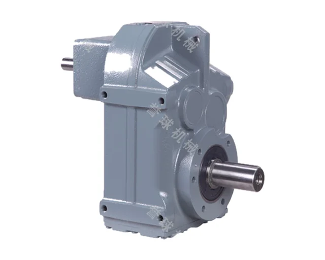
| KF | flange-mounted, solid shaft |
| KAF | flange-mounted, hollow shaft |
| KAZ | short flange, hollow shaft |
| KAT | torque arm, hollow shaft |
| S / AS / FS / AFS (структура) | shaft input instead of motor: foot / hollow / flange / flange + hollow |
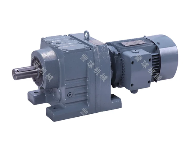
| K..R.. | combined unit with R helical gear unit (motor or shaft input) |
| Y(Y2) | standard motor |
| B | flame-proof |
| Z | direct current |
| YEJ | with brake |
| D | multi-speed |
| YVP | variable frequency |
| YCT | electromagnetic speed modulation |
| R | hoisting/metallurgy duty |
| YVPJ | variable frequency with brake |
| G | roller-table duty |
Mounting
- M1
- M2
- M3
- M4
- M5
- M6
Technical data
Input power, ratios and permissible torque by size
| Size | Input power, kW | Ratio | Permissible torque, Nm |
|---|---|---|---|
| 37 | 0.18~3.0 | 5.36~106.38 | 200 |
| 47 | 0.18~3.0 | 5.81~131.87 | 400 |
| 57 | 0.18~5.5 | 6.57~145.14 | 600 |
| 67 | 0.18~5.5 | 7.14~144.79 | 820 |
| 77 | 0.37~11 | 7.24~192.18 | 1550 |
| 87 | 0.75~22 | 7.19~197.37 | 2700 |
| 97 | 1.1~30 | 8.95~176.05 | 4300 |
| 107 | 3~45 | 8.74~141.46 | 8000 |
| 127 | 7.5~90 | 8.68~146.07 | 13000 |
| 157 | 11~160 | 12.65~150.41 | 18000 |
| 167 | 11~200 | 17.28~163.91 | 32000 |
| 187 | 18.5~200 | 17.27~180.78 | 50000 |
Gear unit weight
| Size | Weight, kg (mean, for reference) |
|---|---|
| 37 | 11 |
| 47 | 20 |
| 57 | 27 |
| 67 | 33 |
| 77 | 57 |
| 87 | 85 |
| 97 | 130 |
| 107 | 250 |
| 127 | 380 |
| 157 | 610 |
| 167 | 1015 |
| 187 | 1700 |
Data from the manufacturer’s catalogue. Full selection tables and dimension drawings are in the PDF catalogue.
Drawings