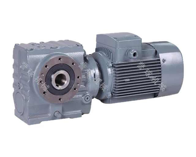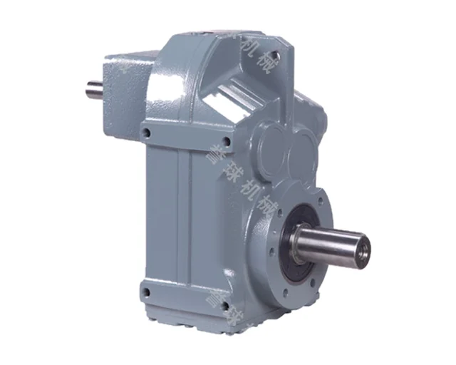
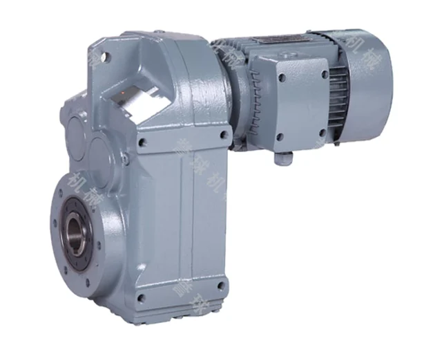
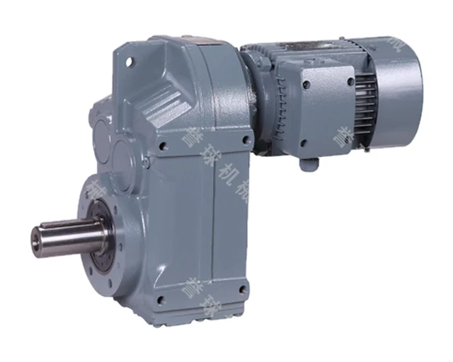
YQF
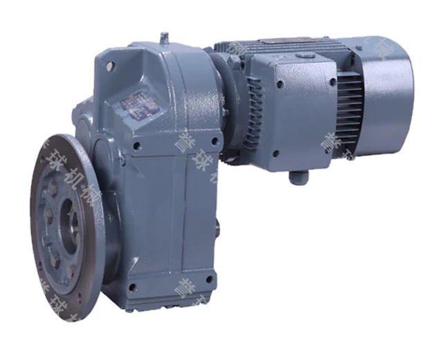
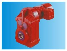
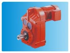
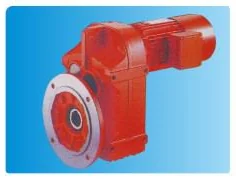
YQF (F) series parallel shaft helical geared motors
Compact parallel shaft helical geared motors: 10 sizes F37–F157, permissible output torque 200–18000 Nm, motors 0.18–200 kW. Solid or hollow output shaft (shaft-mounted on the driven machine), foot, flange and short-flange versions.
- Sizes
- 37, 47, 57, 67, 77, 87, 97, 107, 127, 157
- Ratio
- 3.81–281.71 (F..R combinations higher)
- Motor power
- 0.18–200 kW
- Permissible output torque
- 200–18000 Nm
- Hollow shaft
- ⌀30H7 (F37) … ⌀120H7 mm (F157)
- Rating basis
- selection tables for n₁ = 1400 r/min
- Efficiency
- up to 96 %
- Ambient temperature
- −40…+50 °C (oil to be heated below 0 °C)
- Altitude
- up to 1000 m
- Input speed
- max. 1800 r/min; gear peripheral speed ≤ 22 m/s
- Rotation
- forward and reverse
- Motors
- Y-series, IP54 as standard; brake, flame-proof, inverter-duty and other versions
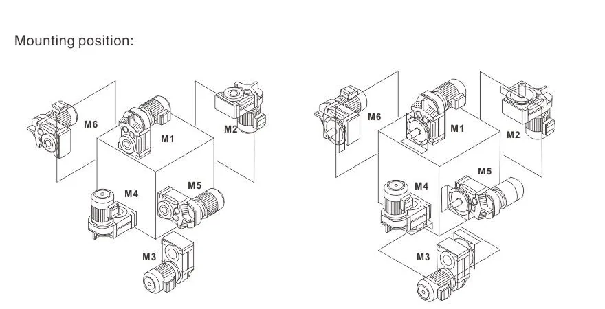
- Mounting positions
- M1–M6 (M1 default); terminal box 0°/90°/180°/270° (0° default)
- Selection
- f_A = f₁·f₂ (load class and daily hours × starts per hour) must not exceed f_B in the tables
Features
- Flat, compact housing for tight spaces
- Hollow shaft bore H7 from ⌀30 to ⌀120 mm for shaft mounting
- Foot, flange, short flange (FAZ) and input-shaft versions
- Ratios 3.81–281.71; F..R combinations for even lower speeds
- Up to 96 % efficiency, modular design
- Mounting positions M1–M6, four terminal box positions
- Customer motor via AM adapter or AD input shaft; torque arm (F..T)
Designation
F F 37 – Y 0.55-4P – 23.88 – M1 – 270°
| F | type: parallel shaft helical gear unit |
|---|---|
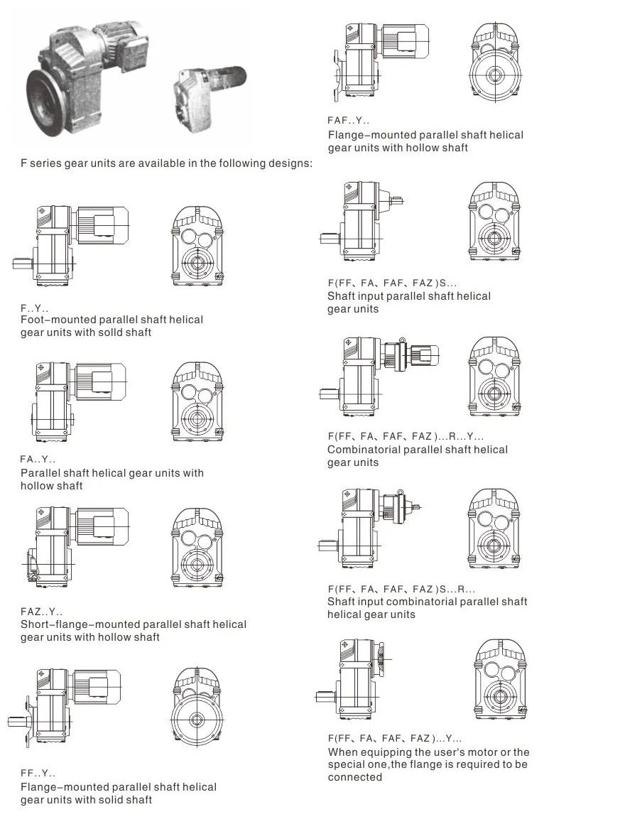
| F | structure: (—) foot, solid shaft; A hollow shaft; F flange; AF flange + hollow shaft; AZ short flange + hollow shaft; S, AS, FS, AFS with input shaft |
| 37 | size |
| Y | motor code (Y, B, Z, YEJ, D, YVP, YCT, R, YVPJ, G) |
| 0.55-4P | motor power, kW, and poles |
| 23.88 | ratio |
| M1 | mounting position M1–M6 |
| 270° | terminal box position 0°/90°/180°/270° |
Versions
| F | foot-mounted, solid shaft |
|---|---|
| FA | hollow output shaft |
| FF | flange-mounted, solid shaft |
| FAF | flange-mounted, hollow shaft |
| FAZ | short-flange-mounted, hollow shaft |
| FS / FAS / FFS / FAFS | with input shaft |
| F..R | combined with R unit for low speeds |
| F..T | with torque arm |
| F..AM / F..AD | IEC motor adapter / input shaft cover |
Mounting
- M1
- M2
- M3
- M4
- M5
- M6
Technical data
F series: power, ratios, torque and hollow shaft by size
| Size | Motor power, kW | Ratio i | Permissible output torque, Nm | Hollow shaft (FA/FAF/FAZ) ⌀ × length, mm | Weight, kg (mean) |
|---|---|---|---|---|---|
| 37 | 0.18~3.0 | 3.81~128.51 | 200 | 30H7 × 120 | 13 |
| 47 | 0.18~3.0 | 5.06~189.39 | 400 | 35H7 × 150 | 17 |
| 57 | 0.18~5.5 | 5.18~199.70 | 600 | 40H7 × 166 | 34 |
| 67 | 0.18~5.5 | 4.21~228.99 | 820 | 40H7 × 180 | 55 |
| 77 | 0.37~11 | 4.30~281.71 | 1500 | 50H7 × 210 | 90 |
| 87 | 0.75~22 | 4.12~270.68 | 3000 | 60H7 × 240 | 150 |
| 97 | 1.1~30 | 4.68~280.76 | 4300 | 70H7 × 300 | 260 |
| 107 | 2.2~45 | 6.20~254.40 | 7840 | 90H7 × 350 | 402 |
| 127 | 7.5~90 | 4.63~172.17 | 12000 | 100H7 × 410 | 700 |
| 157 | 11~200 | 11.92~267.43 | 18000 | 120H7 × 500 | 950 |
Data from the manufacturer’s catalogue. Full selection tables and dimension drawings are in the PDF catalogue.
Drawings