SWL
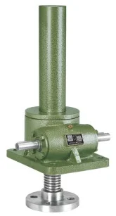
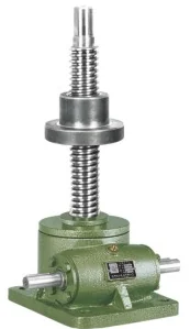
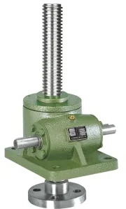
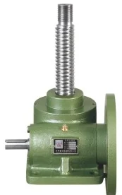
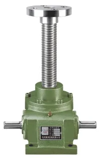
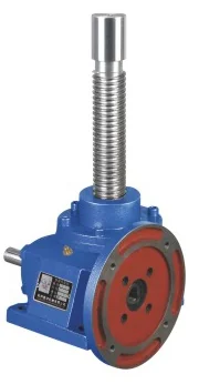
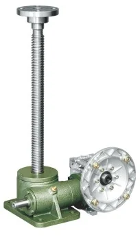
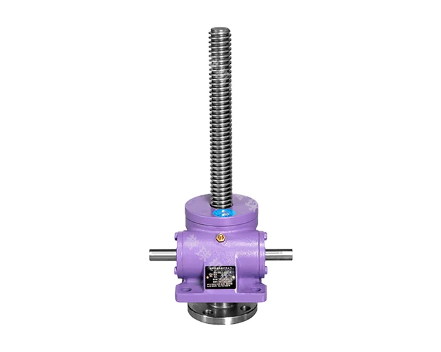
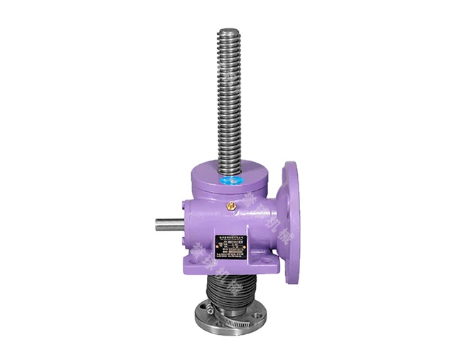
SWL worm gear screw jacks
SWL jacks combine a worm gear and a trapezoidal screw in one compact unit for lifting, lowering, pushing and precise positioning. Capacities range from 0.5 to 100 t (5–1000 kN) with two ratios: normal (P) and slow (M). They are driven by a motor, another power source or by hand, singly or in groups.
- Rated load
- 5–1000 kN (0.5–100 t): 0.5, 1, 2.5, 5, 10, 15, 20, 25, 35, 50, 100 t
- Screw
- trapezoidal, Tr16×4 to Tr160×23
- Ratio P (normal)
- 6:1 to 14.5:1
- Ratio M (slow)
- 22:1 to 36:1
- Lift per worm revolution
- P: 0.364–1.6 mm; M: 0.182–0.638 mm
- Max allowable power
- 0.37–28.5 kW (at 20 °C, 20 %/h duty, worm 1500 r/min)
- Total efficiency
- P: 13–23 %; M: 10–15 % (grease lubricated)
- Lifting speed
- lift per revolution × worm speed; SWL2.5 at 1500 r/min: 1.5 m/min (P), 0.375 m/min (M); per size see catalogue Tables 4–12
- Mass without screw
- 1.75–1010 kg
- Ambient temperature
- −20 to +80 °C
- Lubrication
- grease, top up in good time
Features
- Capacity 0.5–100 t in 11 sizes
- Two ratios: normal (P) and slow (M)
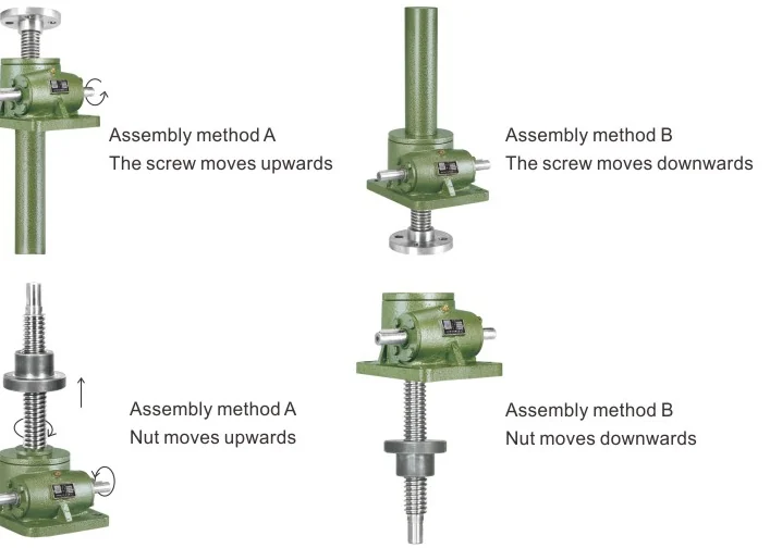
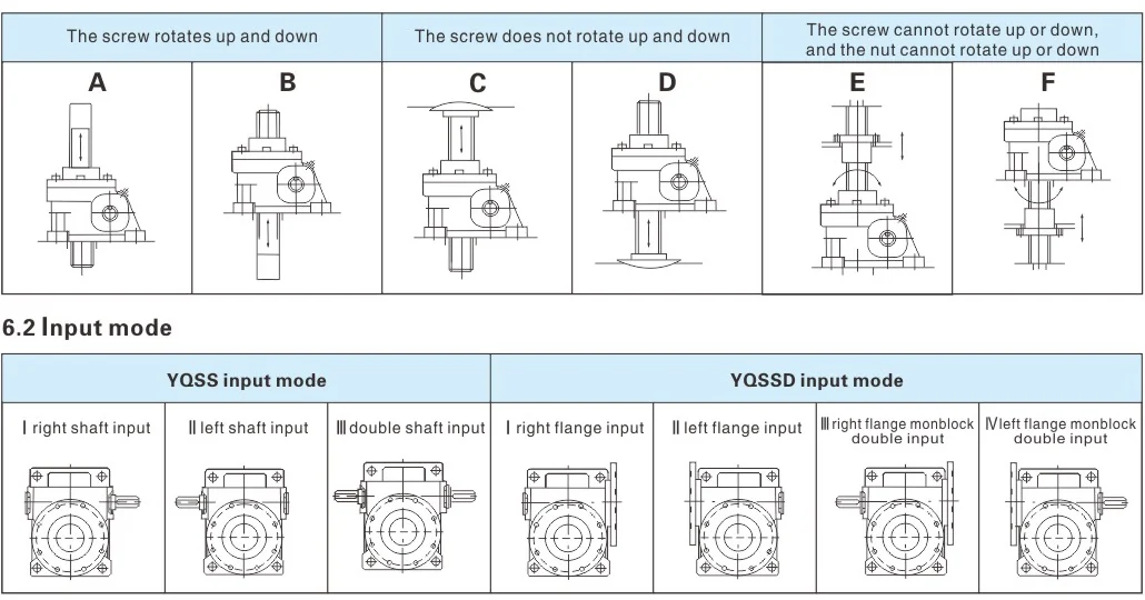
- Type 1: screw travels axially; Type 2: screw rotates, nut travels
- Assembly A (travel upwards) or B (travel downwards)
- Screw ends: cylindrical, flange, threaded, flat head
- Options: anti-rotation (F), protective cover (Z), direct motor mounting
- Generally self-locking at standstill
- Used in machinery, metallurgy, construction, water works, chemicals, medical equipment
Designation
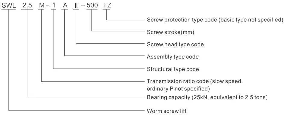
SWL2.5M-1AⅡ-500FZ
| SWL | worm screw jack |
|---|---|
| 2.5 | capacity (25 kN = 2.5 t) |
| M | slow ratio (normal P not marked) |
| 1 | structural type (1 or 2) |
| A | assembly type (A up, B down) |
| Ⅱ | screw head: Ⅰ cylindrical, Ⅱ flange, Ⅲ threaded, Ⅳ flat head |
| 500 | screw stroke, mm |
| FZ | screw protection: F anti-rotation, Z cover (basic not marked) |
Versions
| 1A / 1B | Type 1: screw travels up / down |
|---|---|
| 2A / 2B | Type 2: nut travels up / down on rotating screw |
| Ⅰ / Ⅱ / Ⅲ / Ⅳ | screw ends: cylindrical (R), flange (T), threaded (S), flat head (H); Type 2 only Ⅰ and Ⅲ |
| F | anti-rotation (Type 1) |
| Z | protective screw cover |
| D-type | version with housing flange |
| 2.5T–35T | direct motor connection; also hand wheel or worm gearmotor drive |
Technical data
Main performance parameters (Table 3)
| Model | Max lifting force, kN | Max tensile force, kN | Screw thread | Ratio P | Lift per rev (P), mm | Ratio M | Lift per rev (M), mm | Max power, kW | Efficiency P, % | Efficiency M, % | Mass w/o screw, kg |
|---|---|---|---|---|---|---|---|---|---|---|---|
| SWL0.5 | 5 | 5 | Tr16×4 | 11:1 | 0.364 | 22:1 | 0.182 | 0.37 | — | — | 1.75 |
| SWL1 | 10 | 10 | Tr22×4 | 6:1 | 0.8 | 24:1 | 0.21 | 0.43 | — | — | 3.9 |
| SWL2.5 | 25 | 25 | Tr30×6 | 6:1 | 1.0 | 24:1 | 0.250 | 1.45 | 23 | 14 | 7.3 |
| SWL5 | 50 | 50 | Tr40×7 | 8:1 | 0.875 | 24:1 | 0.292 | 2.59 | 21 | 12 | 16.2 |
| SWL10/15 | 100/150 | 99 | Tr58×12 | 7 2/3:1 | 1.565 | 24:1 | 0.5 | 3.47 | 23 | 15 | 25 |
| SWL20 | 200 | 166 | Tr65×12 | 8:1 | 1.5 | 24:1 | 0.5 | 4.02 | 21 | 13 | 36 |
| SWL25 | 250 | 250 | Tr90×16 | 10 2/3:1 | 1.5 | 32:1 | 0.5 | 5.38 | 19 | 11 | 70.5 |
| SWL35 | 350 | 350 | Tr100x20 | 10 2/3:1 | 1.5 | 32:1 | 0.56 | 13.6 | 18 | 11 | 87 |
| SWL50 | 500 | 500 | Tr120x20 | 12.5:1 | 1.6 | 32:1 | 0.625 | 13.9 | 15 | 11 | 420 |
| SWL100 | 1000 | 1000 | Tr160x23 | 14.5:1 | 1.586 | 36:1 | 0.638 | 28.5 | 13 | 10 | 1010 |
Direct motor connection
| Model | Motor power, kW | Shaft d, mm | Flange LA/LB/LC, mm | Lift force P, kN | Lift force M, kN |
|---|---|---|---|---|---|
| 2.5T | 0.25/0.37 | 14 | 130/110/160 | 3.4 | 8.2 |
| 5T | 0.75 | 19 | 165/130/200 | 7.1 | 12.3 |
| 10T/15T | 1.1/1.5 | 24 | 165/130/200 | 8.8 | 18 |
| 20T | 3.0 | 28 | 215/180/250 | 16.8 | 31 |
| 25T | 4.0 | 28 | 215/180/250 | 30.4 | 52.8 |
| 35T | 4.0 | 28 | 215/180/250 | 28 | 52.8 |
Data from the manufacturer’s catalogue. Full selection tables and dimension drawings are in the PDF catalogue.
Drawings