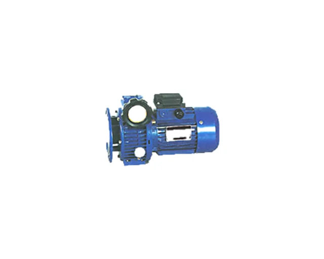
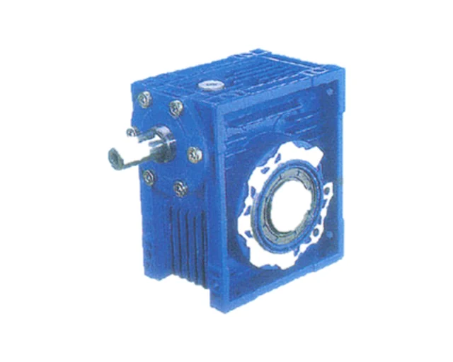
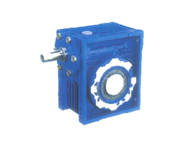
YQNMRV
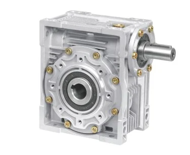
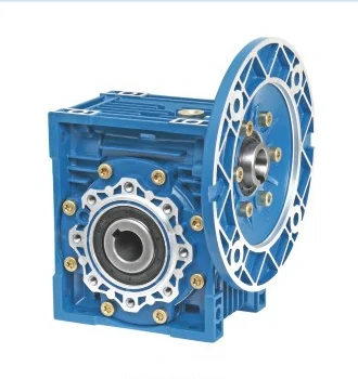
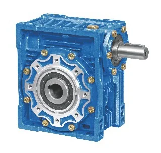
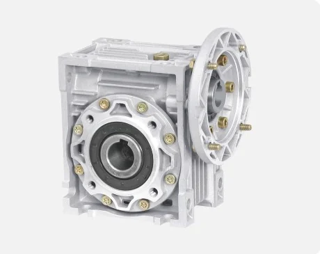
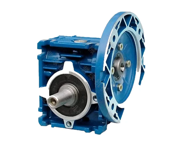
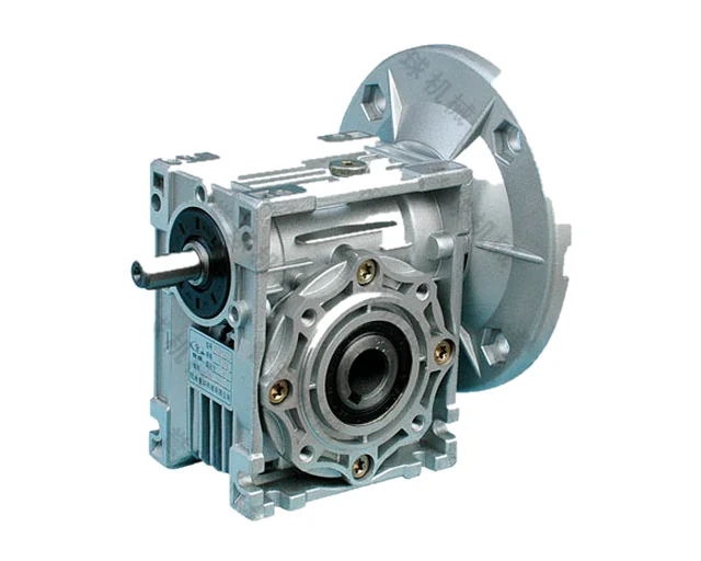
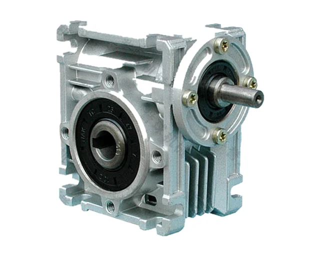
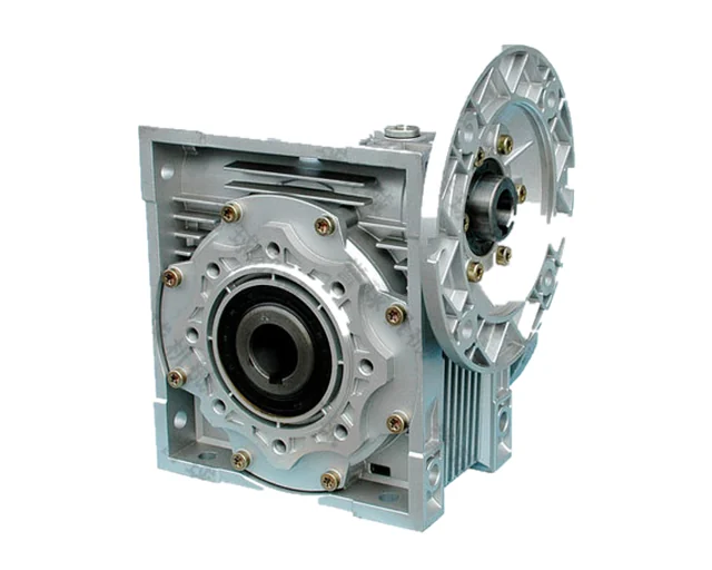
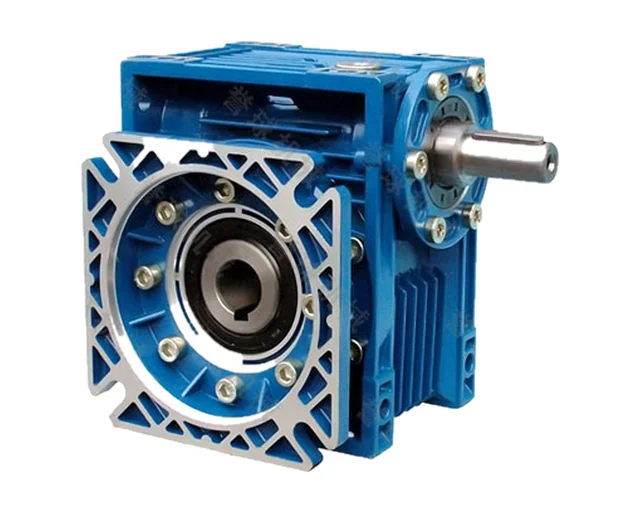
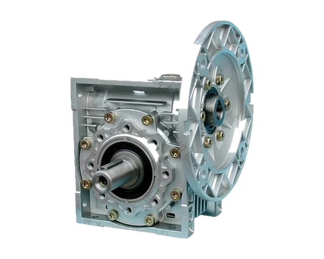
NMRV / NRV single-stage worm gear reducers
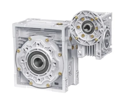
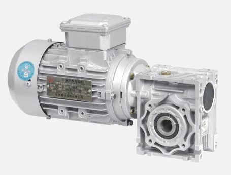
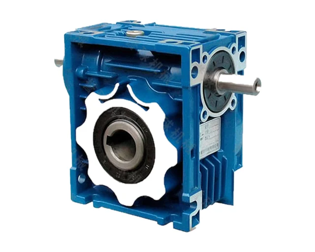
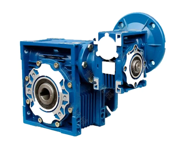
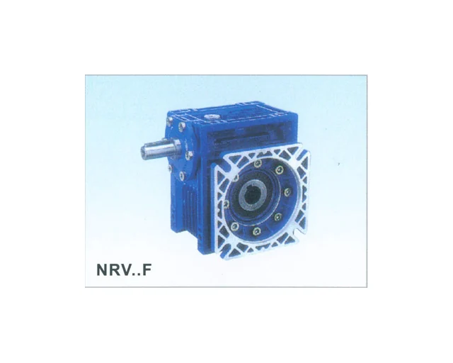
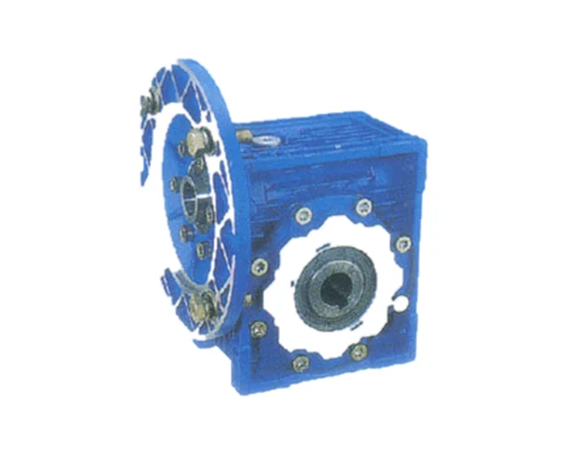
Single-stage worm gear reducers in sizes 025–150 with a hollow output shaft. The NMRV version takes an IEC motor directly through an input flange and hollow input bore; the NRV version has a solid input shaft for a coupling or pulley. Ratios from 5 to 100 with a wide choice of output shafts, flanges and mounting positions.
- Sizes
- NMRV: 025, 030, 040, 050, 063, 075, 090, 110, 130, 150; NRV: 030–150
- Centre distance
- 25–150 mm
- Ratio
- 5–100 (5, 7.5, 10, 15, 20, 25, 30, 40, 50, 60, 80, 100)
- Motor power (NMRV tables, 4-pole, 1400 r/min)
- 0.06–15 kW
- Output speed (1400 r/min input)
- 14–186.7 r/min
- Output torque (selection tables)
- NMRV: 2.4–1452 N·m; NRV: 13–1550 N·m
- Hollow output bore
- Ø11–50 mm, H8
- NRV input shaft
- Ø9–35 mm, j6
- Housing material
- 025–090 die-cast aluminium alloy; 110–150 cast iron
- Lubrication
- 025–090: synthetic oil ISO VG 320 (−25…+50 °C); 110–130: mineral oil ISO VG 460 (−5…+40 °C) or ISO VG 220 (−5…+25 °C)
- Oil quantity (110 / 130 / 150, position B3)
- 2.5 / 4 / 5.4 l
- Max. oil temperature
- 95 °C
- Recommended input speed
- not above 1500 r/min
- Oil change
- first after 800 h, then about every 1500 h
- Weight without motor
- ≈0.7 kg (025) – 84 kg (150)
Features
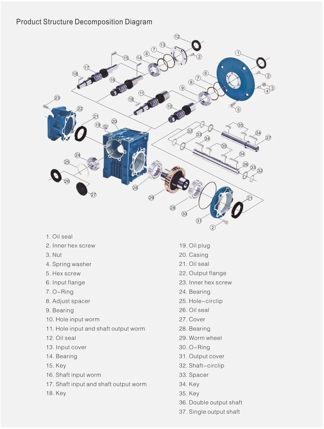
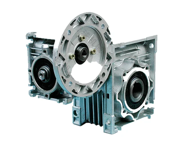
- Sizes 025–090 have die-cast aluminium alloy housings: light, compact and corrosion-resistant
- Sizes 110–150 use a cast-iron housing for heavier duty
- Finned housing gives good heat dissipation; smooth running with low noise and vibration
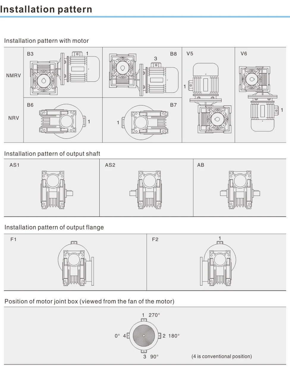
- Input options: IEC motor flange (B5/B14, frames 56–160), free input shaft, or double-ended input shaft (VS)
- H8 hollow output bore; plug-in output shafts available, single (AS) or double (AB)
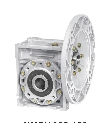
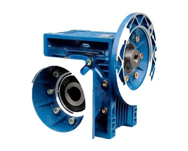
- Output flanges FA–FE and a torque arm for shaft-mounted installation
- Feet and fixing holes on several faces allow many mounting positions
- Right-hand worm helix
Designation
NMRV 063-40-80B5-AS1-B3
| NMRV | worm reducer with hollow input and motor flange (NRV = shaft input) |
|---|---|
| 063 | size |
| 40 | ratio |
| 80B5 | motor flange (IEC frame); motor power may be given instead, e.g. 0.75 kW |
| VS | (option) double input shaft |
| AS1 | output: AS1/AS2 single shaft, AB double shaft, F… output flange |
| B3 | mounting position |
Versions
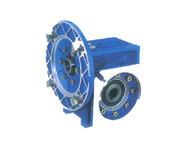
| NMRV | Hollow input with IEC B5/B14 flange for direct motor mounting (sizes 025–150) |
|---|---|
| NRV | Free solid input shaft (sizes 030–150) |
| VS | Double-ended input shaft |
| AS1 / AS2 | Single output shaft, left or right side |
| AB | Double output shaft |
| F1 / F2 | Output flange on either side; flange types FA (025–150), FB (040–110), FC and FD (040, 050, 063, 090), FE (063) |
| Torque arm | Torque arm for shaft-mounted use (025–150) |
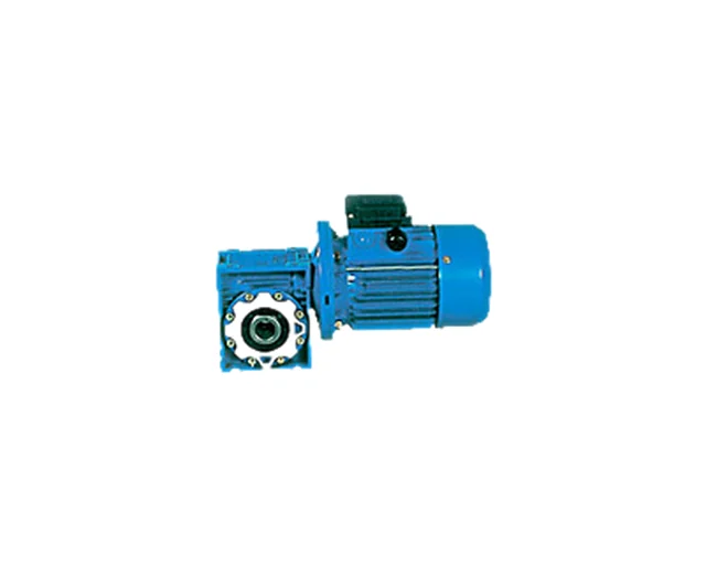
| NMRV + motor | Gearmotor: NMRV assembled with an electric motor |
Mounting
- B3
- B8
- B6
- B7
- V5
- V6
Technical data
Main dimensions, mm
| Size | Centre distance I | Hollow bore D (H8) | NRV input shaft D1 (j6) | G1 | H | Weight without motor, ≈ kg |
|---|---|---|---|---|---|---|
| 025 | 25 | 11 | - | - | - | 0.7 |
| 030 | 30 | 14 | 9 | 63 | 40 | 1.2 |
| 040 | 40 | 18 (19) | 11 | 78 | 50 | 2.3 |
| 050 | 50 | 25 (24) | 14 | 92 | 60 | 3.5 |
| 063 | 63 | 25 (28) | 19 | 112 | 72 | 6.2 |
| 075 | 75 | 28 (35) | 24 | 120 | 86 | 9 |
| 090 | 90 | 35 (38) | 24 | 140 | 103 | 13 |
| 110 | 110 | 42 | 28 | 155 | 127.5 | 35 |
| 130 | 130 | 45 | 30 | 170 | 147.5 | 48 |
| 150 | 150 | 50 | 35 | 200 | 170 | 84 |
NRV: output torque, N·m (input power, kW); input 1400 r/min
| i | n2, r/min | NRV030 | NRV040 | NRV050 | NRV063 | NRV075 | NRV090 | NRV110 | NRV130 | NRV150 |
|---|---|---|---|---|---|---|---|---|---|---|
| 7.5 | 186.7 | 18 (0.4) | 40 (0.9) | 71 (1.6) | 128 (2.8) | 185 (4.1) | 290 (6.3) | 552 (12) | 750 (16.1) | 1200 (25.8) |
| 10 | 140 | 18 (0.3) | 40 (0.7) | 72 (1.2) | 130 (2.2) | 195 (3.2) | 310 (5.1) | 598 (9.8) | 820 (13.5) | 1240 (20.2) |
| 15 | 93.3 | 18 (0.2) | 40 (0.5) | 74 (0.9) | 140 (1.6) | 200 (2.3) | 360 (4.1) | 656 (7.5) | 920 (10.3) | 1250 (13.9) |
| 20 | 70 | 18 (0.2) | 39 (0.4) | 73 (0.7) | 135 (1.2) | 210 (1.9) | 355 (3.1) | 644 (5.6) | 910 (7.8) | 1300 (11.1) |
| 25 | 56 | 21 (0.2) | 38 (0.3) | 70 (0.5) | 130 (1.0) | 200 (1.5) | 340 (2.4) | 679 (4.7) | 930 (6.5) | 1200 (8.4) |
| 30 | 46.7 | 20 (0.2) | 45 (0.3) | 84 (0.6) | 160 (1.1) | 230 (1.5) | 410 (2.6) | 725 (4.5) | 1040 (6.4) | 1200 (7.1) |
| 40 | 35 | 18 (0.1) | 41 (0.2) | 76 (0.4) | 145 (0.8) | 220 (1.1) | 360 (1.8) | 702 (3.3) | 1050 (4.9) | 1550 (7.3) |
| 50 | 28 | 17 (0.1) | 39 (0.2) | 73 (0.3) | 135 (0.6) | 210 (0.9) | 340 (1.4) | 660 (2.6) | 980 (3.8) | 1400 (5.4) |
| 60 | 23.3 | 16 (0.1) | 36 (0.2) | 68 (0.3) | 130 (0.5) | 200 (0.8) | 320 (1.1) | 616 (2.1) | 900 (3.1) | 1260 (4.2) |
| 80 | 17.5 | 13 (0.1) | 33 (0.1) | 65 (0.2) | 122 (0.4) | 190 (0.6) | 285 (0.8) | 515 (1.4) | 840 (2.3) | 1150 (3.1) |
| 100 | 14 | - | 29 (0.1) | 55 (0.2) | 118 (0.3) | 180 (0.5) | 270 (0.7) | 483 (1.1) | 740 (1.7) | 1000 (2.3) |
NMRV: IEC motor flanges and available ratios
| Size | PAM IEC flange | Motor shaft D, mm | Ratios i |
|---|---|---|---|
| 025 | 56B14 | 9 | 5–20, 30–60 |
| 030 | 63B5 / 63B14 | 11 | 5–50 |
| 030 | 56B5 / 56B14 | 9 | 5–80 |
| 040 | 71B5 / 71B14 | 14 | 5–40 |
| 040 | 63B5 / 63B14 | 11 | 5–100 |
| 040 | 56B5 | 9 | 50–100 |
| 050 | 80B5 / 80B14 | 19 | 5–30 |
| 050 | 71B5 / 71B14 | 14 | 5–80 |
| 050 | 63B5 | 11 | 40–100 |
| 063 | 90B5 / 90B14 | 24 | 7.5–30 |
| 063 | 80B5 / 80B14 | 19 | 7.5–60 |
| 063 | 71B5 / 71B14 | 14 | 40–100 |
| 075 | 100/112B5 / 100/112B14 | 28 | 7.5–15 |
| 075 | 90B5 / 90B14 | 24 | 7.5–40 |
| 075 | 80B5 / 80B14 | 19 | 20–100 |
| 075 | 71B5 | 14 | 50–100 |
| 090 | 100/112B5 / 100/112B14 | 28 | 7.5–30 |
| 090 | 90B5 / 90B14 | 24 | 7.5–60 |
| 090 | 80B5 / 80B14 | 19 | 40–100 |
| 110 | 132B5 | 38 | 7.5–20 |
| 110 | 100/112B5 | 28 | 7.5–60 |
| 110 | 90B5 | 24 | 25–100 |
| 110 | 80B5 | 19 | 80–100 |
| 130 | 132B5 | 38 | 7.5–40 |
| 130 | 100/112B5 | 28 | 25–100 |
| 130 | 90B5 | 24 | 80–100 |
| 150 | 160B5 | 42 | 7.5–25 |
| 150 | 132B5 | 38 | 20–60 |
| 150 | 100/112B5 | 28 | 50–100 |
Data from the manufacturer’s catalogue. Full selection tables and dimension drawings are in the PDF catalogue.
Drawings